")
")
Loading ramp made of concrete slabs

The space between the two loading tracks (grain storage, warehouse, livestock loading) is to be covered with concrete slabs. The height of the covering should reach just below the top of the rails (approx. 8 mm). First, we made a paper template of the space between the tracks and cut it out to fit exactly. This was transferred to a 6 mm thick poplar wood panel (the cheapest option!). We then cut out the panel using a jigsaw and screwed it in place with Spax screws. One of our stacking boards serves as a precise stop at the edge of the module. Further information to follow.
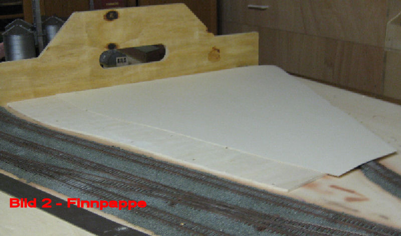
The next step was to cut a piece of Finnboard (1 mm) to size using a template made as described above and glue it onto the wooden panel. The cardboard can be cut with scissors or a craft knife/scalpel (for information on the materials mentioned in the following pictures and text and where to obtain them, see the Construction Instructions menu).
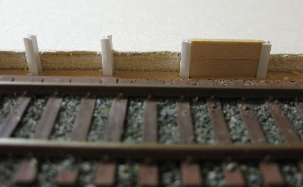
At the track (which is also where the livestock is loaded), goods can be transferred directly from the truck to the railway vehicles. For this purpose, part of this track is equipped with a loading edge. It consists of vertically installed plastic H-beams and 1 x 5 mm thick wooden strips. The distance between the individual beams is 2 cm. Contrary to the photo, we will only install one “board.” We drilled suitable holes (3.5 drill bit) in the base plate for the H-beams.
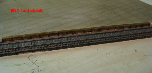
Loading edge - First, coat a 1x5 mm lime wood strip with wood stain. This strip was glued to the top of the concrete slab covering with Ponal Express. This strip serves as a protective barrier for road vehicles (stop here and no further!). Next, the H-beams, which had been painted dust brown beforehand, were glued into the pre-drilled holes with Ponal. Now cut a lime wood strip to the appropriate length, glue the pieces between the beams, and stain the wooden stiffeners. I applied the stain to the wooden parts twice. Done!
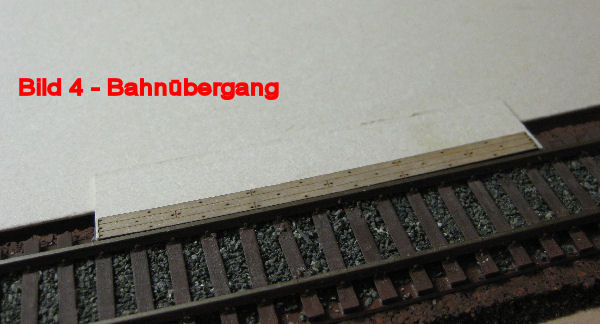
A railroad crossing will open up the area for road vehicles. The current structure has now reached approximately the height of the top of the sleepers. Next, a piece of Finnboard (1 mm) cut to size will fill the gap between the top of the sleepers and the top of the small iron. A wooden strip from the laser-cut set will then be glued onto this. This now extends to just below the top of the rails.
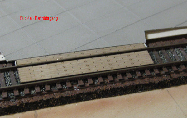
Railroad crossing - The space between the rails is filled with the parts from the laser-cut kit. Before gluing, the exact position must be determined with a locomotive to prevent the wheel sets from running onto the wooden strip. The second outer strip is only installed once the terrain on this side of the rail has been installed.
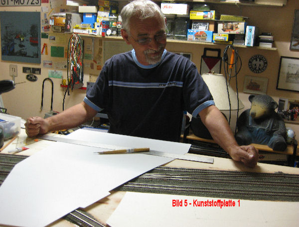
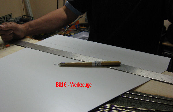
Image 5 - A 1 mm thick plastic sheet is now placed on top of the structure that has been built so far. We have again made a paper template to cut out the sheet precisely. The sheet can be cut out with a sharp craft knife or scalpel.
Image 6 - Now the joints between the individual concrete slabs need to be scored. The individual slabs will measure 4 x 2 cm. We have transferred the dimensions onto the slab with a pencil. The joints are scored using a scribing tool. To ensure that the joints are perfectly straight, we guide the tool along an aluminum rail.
Bernd, who is supposed to carry this out, even though he plugged in the cable reel three hours ago, received the aluminum rail as a gift from a customer. The rest of the aluminum plate was installed in a Mercedes truck a good 20 years ago, as befits its status. So if you own a Mercedes truck that is around 20 years old, please send our regards!
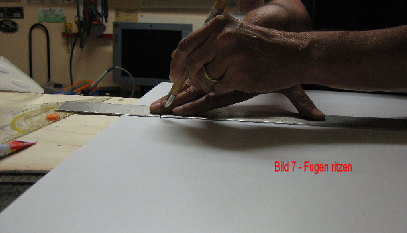
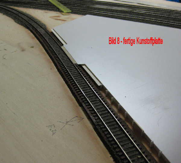 Image 7 - The engraving process! Five passes of the needle along the rail and you have a nice joint... but sore fingers too! Thankfully, Andy does this work at the container terminal!
Image 8 - The finished plate - nothing to see with our photography skills! But the color will follow! In this photo, you can clearly see the magnet for the decoupler of the Kadee couplings.
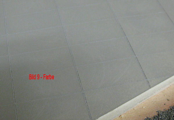
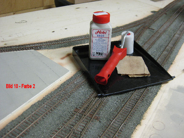
Image 9 - After engraving, the plastic plate is colored with Heki road paint in “concrete.” A paint roller was used for this. After drying, the painted surface feels rough. To enhance the contours, the paint can be sanded down with fine sandpaper.
Image 10 - The materials used.
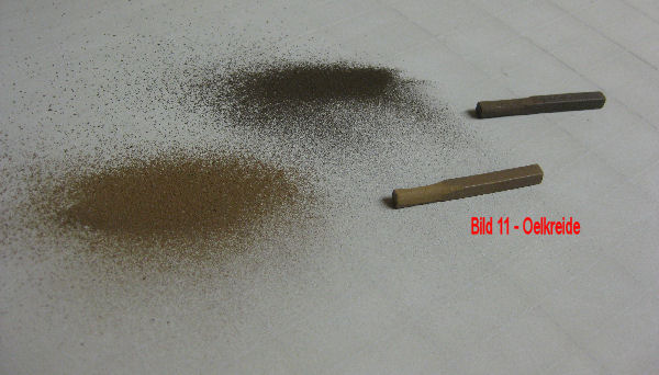
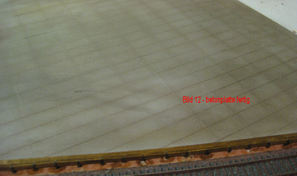
Image 11 - Aging/soiling is applied using artist's chalk (oil chalk). Two different colored sticks are used for this. A scalpel is used to lightly scratch the surface of the sticks. This creates a fine dust. This dust is rubbed into the paint using a brush that is not too hard. The fine chalk dust also remains in the joints.
Image 12 - The finished panel. Now Andy can only worry about how to spray on tire tracks or cow pats.
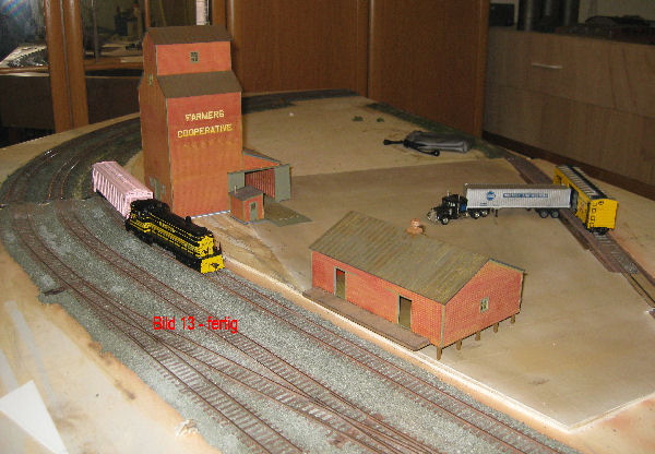
Image 13 - The finished loading bay with the approximate location of the buildings - The “camera bag” is NOT glued in place! Complaints from Manuela!
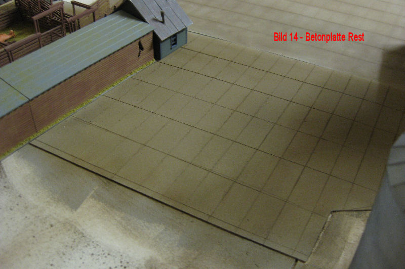
Image 14 - The remaining part of the concrete slab on the turning module.
.